Staggered extrusion type light steel keel low-position cement grouting equipment

A light steel keel and cement grouting technology, applied in the field of light steel keel, can solve the problems of increased workload, casualties, artificial falls, etc., and achieve the effect of avoiding waste and uniform coverage

Active Publication Date: 2022-05-17
安徽鹏佳建设有限公司
View PDF7 Cites 0 Cited by
  • Summary
  • Abstract
  • Description
  • Claims
  • Application Information

AI Technical Summary

Problems solved by technology

[0005] In order to overcome that when the sack is removed, the cast wall will also leave a pit. At the same time, when pouring the upper part of the light steel keel wall, because the wall is too high, manual operations often need to stand on the scaffold. During the pouring process, it is very easy to cause artificial fall, resulting in casualties, and at the same time, the workload will be greatly increased. The invention provides a dislocation extrusion type cement grouting equipment for the lower part of the light steel keel

Method used

View more

Image

Smart Image Click on the blue labels to locate them in the text.
Viewing Examples
Smart Image
  • Staggered extrusion type light steel keel low-position cement grouting equipment
  • Staggered extrusion type light steel keel low-position cement grouting equipment
  • Staggered extrusion type light steel keel low-position cement grouting equipment

Examples

Experimental program
Comparison scheme
Effect test

Embodiment 1

[0036] A dislocation extrusion type cement grouting equipment at the lower part of the light steel keel, such as Figure 1-13 As shown, it includes base plate 1, casters 2, housing 3, handle 4, barrier system, laminating system and slurry screed system; four corners of the lower side of base plate 1 are connected with casters 2; the upper side of base plate 1 is connected with shell Body 3; a handle 4 is connected to the middle part on the left side of the casing 3; a barrier system is arranged above the casing 3; a fitting system is connected inside the casing 3; three slurry screed systems distributed up and down are connected to the fitting system ; The three slurry screed systems have the same structure.

[0037] Working process: When using this misplaced extruded light steel keel low cement grouting equipment, the operator first connects the barrier system bolts between the two vertical keels of the light steel keel wall, and then places the plate on the barrier system T...

Embodiment 2

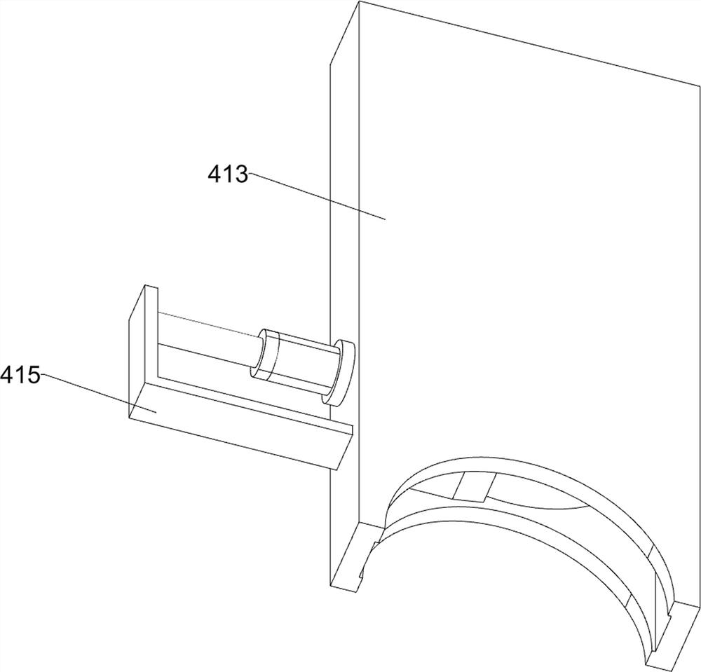
[0052] On the basis of Example 1, such as figure 1 and Figure 14-16 As shown, it also includes a snapping system; the upper side of the housing 3 is connected with the snapping system; the snapping system is located in front of the barrier system; the snapping system includes a fixed seat 401, an electric slide rail 402, an electric slider 403, a second Four connecting plates 404, electric push rod 405, second disk 406, fifth connecting plate 407, third L-shaped plate 408, second circular tube 409, bracket 410, fourth elastic column 411, third wedge-shaped block 412, Storage box 413, small push rod 414 and fourth L-shaped plate 415; housing 3 upper side is fixedly connected with fixed base 401; fixed base 401 upper side bolt is connected with electric slide rail 402; electric slide rail 402 is slidingly connected with electric The slider 403; the upper side of the electric slider 403 is fixedly connected with the fourth connecting plate 404; the bolt on the upper rear side o...

Login to view more

PUM

No PUM Login to view more

Abstract

The invention relates to the technical field of light steel keels, in particular to dislocation extrusion type low-position cement grouting equipment for a light steel keel. The technical problems that when a jute bag is dismantled, a pit is left in a poured wall body, meanwhile, when the upper half part of the wall body is poured, due to the fact that the wall body is too high, workers often need to stand on a scaffold to operate, the workers fall off easily in the pouring process, and casualties are caused are solved. According to the technical scheme, the staggered extrusion type light steel keel low position cement grouting equipment comprises an attaching system and the like; and a laminating system is connected in the shell. By means of the attaching system, the light steel keel wall is attached and extruded in a staggered mode, deformation or bursting caused by the fact that slurry suddenly exerts overlarge pressure on grids on the light steel keel wall when cement grouting equipment at the low position of the staggered extrusion type light steel keel is withdrawn is prevented, meanwhile, the slurry ironing system is matched, and the cement grouting equipment is not prone to deformation or bursting. A large amount of cement paste overflowing from the light steel keel wall is collected and treated, and waste is avoided.

Description

technical field [0001] The invention relates to the technical field of light steel keels, in particular to a dislocation extrusion type cement grouting equipment for the lower part of light steel keels. Background technique [0002] Light steel keel is a new type of building material. With the development of my country's modernization construction, it has been widely used in hotels, interior decoration settings, ceilings and other places in recent years. The wall made of light steel keel is light in weight, high in strength, good in fire resistance, not easy to deform, strong in versatility and easy to install. [0003] After the light steel keel house is installed, it is necessary to pour cement into the light steel keel. The current pouring is usually done manually. When pouring, the holes are manually opened on the light steel keel grid in advance, and then through the delivery pipe Carry out its pouring, and after each small piece is poured, the hole is blocked with a s...

Claims

Login to view more

Application Information

Patent Timeline
no application Login to view more
Patent Type & Authority Applications(China)
IPC IPC(8): E04G21/02E04G21/06
CPCE04G21/02E04G21/06
Inventor 王小红
Owner 安徽鹏佳建设有限公司
Who we serve
  • R&D Engineer
  • R&D Manager
  • IP Professional
Why Eureka
  • Industry Leading Data Capabilities
  • Powerful AI technology
  • Patent DNA Extraction
Social media
Try Eureka
PatSnap group products